Gm 3 Bar Map Sensor Wiring Diagram

Gm 3 Bar Map Sensor Calibration G4 Link Engine Management
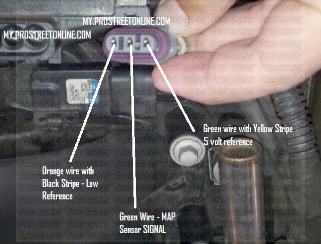
How To Install A 3 Bar Map Sensor My Pro Street

Gm 3 Bar Map Sensor Wiring Diagram Wiring Diagram

16 Map Sensor Wiring Diagram Engine Engine Diagram Wiringg Net In 2020 Map Sensor Sensor Map

Installing A Gm 3 Bar Map Sensor Wire Configuration Help Honda Tech Honda Forum Discussion
Microsquirt Introduction

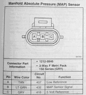
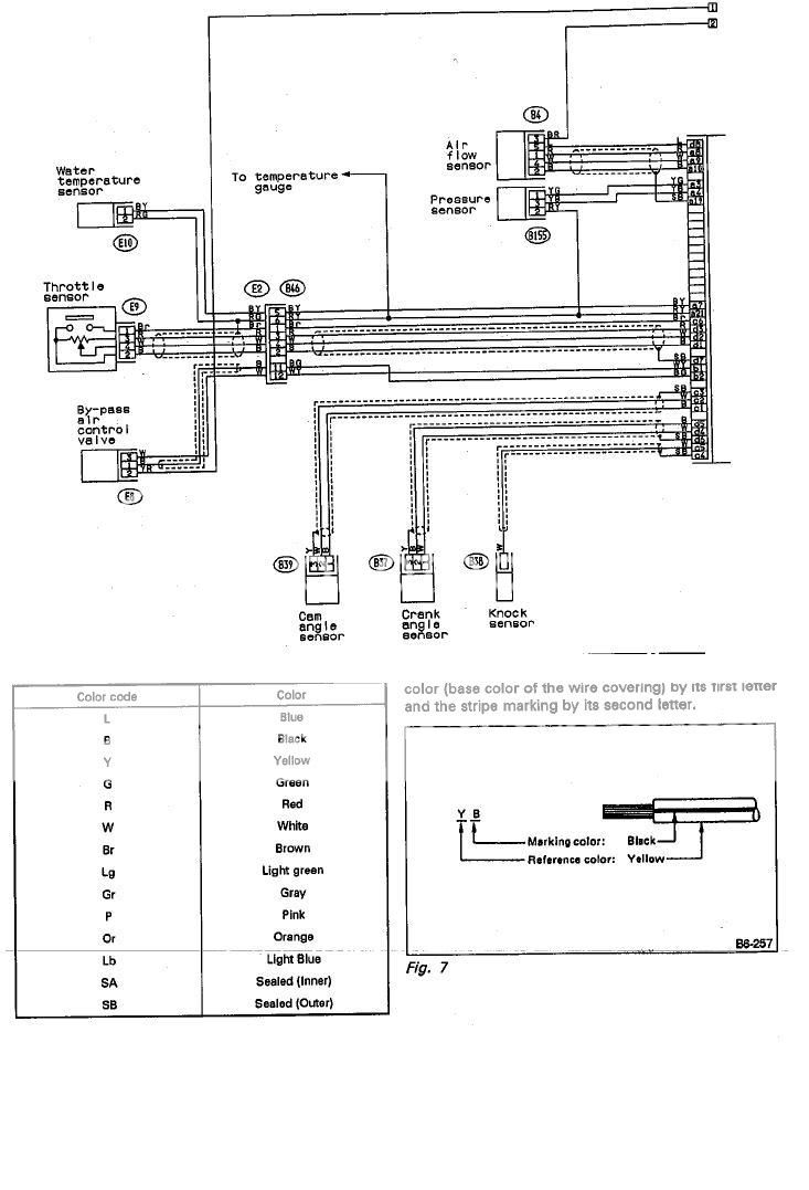
Sensor map 02 airflow tps knock idle solenoid controll coolant temp.
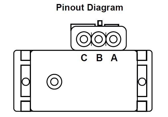
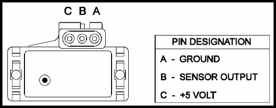
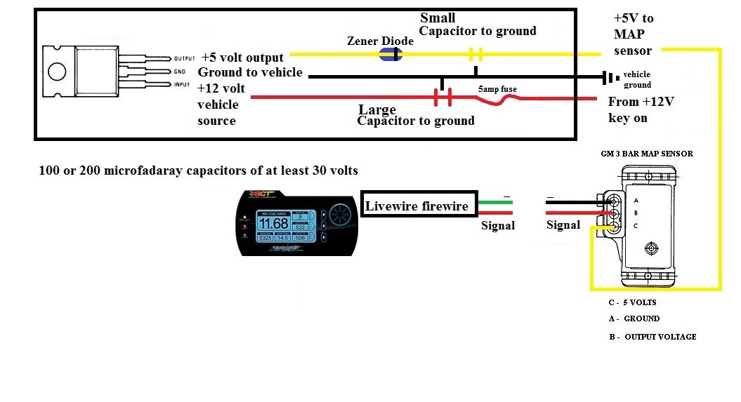
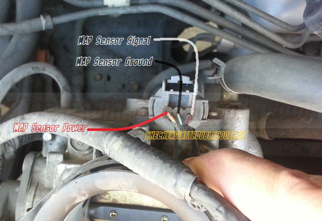
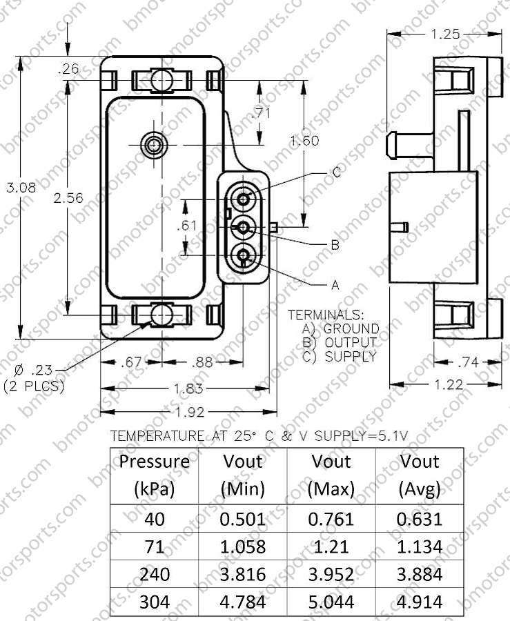
Gm 3 bar map sensor wiring diagram.

Oh 0990 Gmc Map Sensor Wiring Diagram Free Diagram
Wiring Your Gm Map Sensor Iat Sensor For Use With A Csl Clone Ecu Ecuworx
3 Bar Gm Map Sensor Blues Again Miata Turbo Forum Boost Cars Acquire Cats

Gm Map Sensors 1 Bar 2 Bar 3 Bar Wiring Harnesses
Mounting My New 3 Bar Map Ls1tech Camaro And Firebird Forum Discussion
Issue Wiring In Gm Map Sensor For Lw Mustangforums Com

Me 7073 Gm Map Sensor Wiring Diagram Wiring Diagram
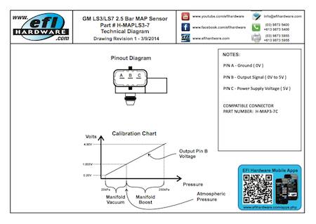
Ls3 Ls7 2 7 Bar Map Sensor
Map Sensor Wiring For 3bar Simtek Scoobynet Com Subaru Enthusiast Forum

Toyota Map Sensor Pinout In 2020 Map Sensor Toyota Electrical Circuit Diagram
Fa3 Gm Map Sensor Wiring Diagram Wiring Resources

Hx 4934 Wiring Map Saab Sensor 9132374 Schematic Wiring

Gm 3 Bar Map Sensor Wiring Honda Gm 3 Bar Map Sensor Calibration G4 Link Engine Management How To Install A 3 Bar Map Sensor My Pro Street Gm 3 Bar Map
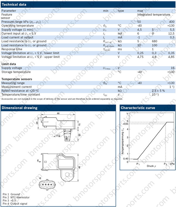
Bosch Map Sensor 0281002316 Engine Tuning Link Engine Management

How To Install A Gm 3 Bar Into A Honda Youtube

Mspb 1723 Gm Map Sensor Diagram Diagram Base Website Sensor Diagram Drawios Boersentag Chemnitz De

Bmw Series 318i Fuse Box 2002 Honda 350 Rancher Wiring Diagram For Wiring Diagram Schematics

Cb 1593 3 Bar Map Sensor Wiring Diagram Wiring Diagram
Https Encrypted Tbn0 Gstatic Com Images Q Tbn 3aand9gctfg5ybuggifoqkxeguxasdmy0ahqgng98dndo 2y4jbzu0l0vg Usqp Cau

3 Bar Gm Style Map Sensor Efi Parts

Map Sensor Wiring Diagram Map Sensor Automotive Repair Car Repair Diy
P1129 Honda 1 6l How To Test A Map Sensor My Pro Street

Dr 8953 Gmc Map Sensor Wiring Diagram Free Diagram
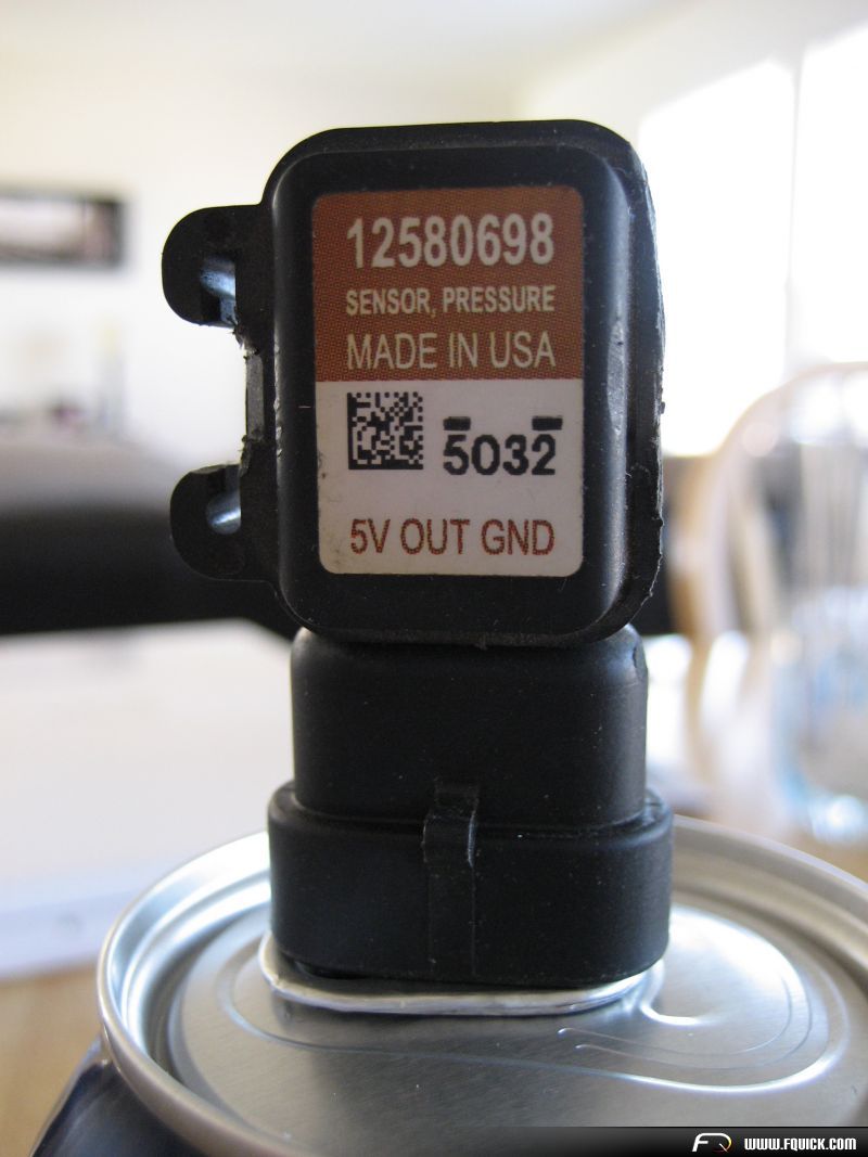
Home Shop Sensors Pressure Sensors Delphi Gm 3 Bar Style Map Sensor 12223861 16040749 Us Made
Source : pinterest.com
